An in-depth explanation of the components and operational principles of an X-ray tube, including the cathode, anode, focal spot, and heat management systems.
The production of X-rays is a remarkably inefficient process. When high-speed electrons strike a target, approximately $99%$ of their kinetic energy is converted into heat, while only about $1%$ is converted into actual X-ray radiation. To manage this extreme thermal load and ensure the precise direction of electron flow, the X-ray tube is engineered as a complex assembly of specialized components housed within a vacuum-sealed environment.
Cross-section of a complete X-ray tube assembly, showing the protective housing, glass envelope, oil, cathode, anode, and window.
The Glass Envelope and Protective Housing
At the core of the system is the glass envelope, typically constructed from Pyrex. This envelope is vacuum-sealed to remove all oxygen, which allows electrons to move freely without interference. Inside this envelope, the cathode and anode are positioned to facilitate electron production and energy conversion. To manage the massive amount of infrared radiation (heat) produced, the envelope is immersed in oil, which serves as both a thermal cushion and an electrical insulator.
The entire assembly is encased in a protective housing. This housing serves two vital roles: it provides mechanical support for the tube and absorbs unwanted leakage radiation. Leakage radiation refers to any radiation that exits the housing through paths other than the intended window. To ensure patient and staff safety, the housing must limit leakage radiation to no more than 1 mGy/hr at a distance of one meter. The X-rays that successfully pass through the designated window of the envelope constitute the useful beam that reaches the patient.
The Cathode: Electron Production
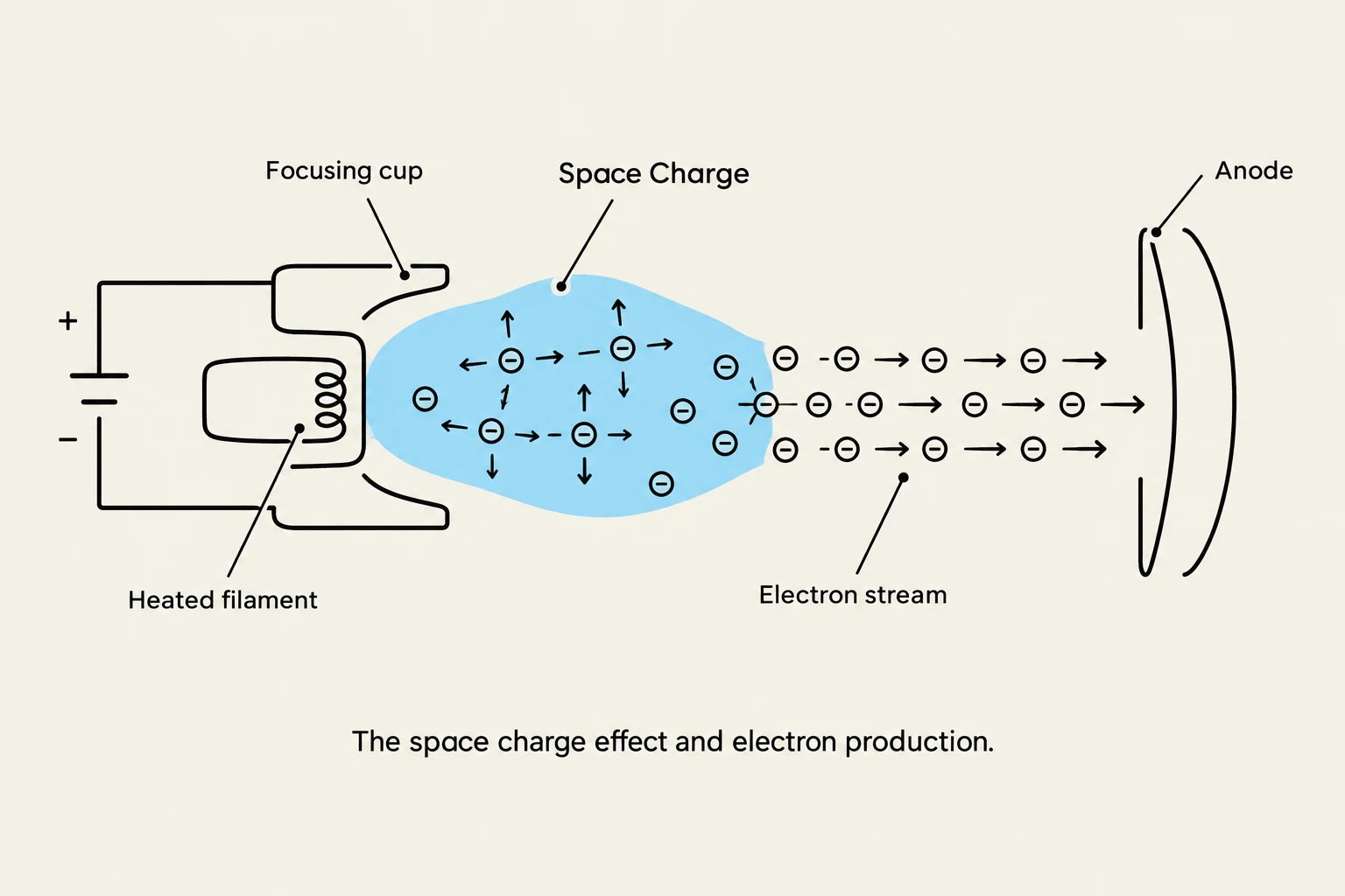
The cathode is the negative side of the X-ray tube and is responsible for producing electrons. It consists of two primary parts: the filaments and a negatively charged focusing cup.
Filaments and Focal Spot Size
Diagram illustrating the space charge effect and electron production in a vacuum tube, showing a heated filament emitting electrons that form a space charge before being accelerated towards the anode.
Most tubes contain one or two filaments, categorized by size:
Small Filament: Used when high spatial resolution (fine detail) is required. While it provides better detail, it results in a longer exposure time and concentrates more heat on a smaller surface area.
Large Filament: Used for quicker exposure times. It allows for higher mA (milliampere) stations and can handle more heat due to its larger surface area, but it results in lower spatial resolution.
The choice of filament directly determines the actual focal spot size, which is the physical area on the anode target where the electron beam strikes.
Space Charge and Saturation
As the filament is heated, it releases a cloud of electrons known as the space charge. The space charge effect is the phenomenon where the tube is unable to "boil off" more electrons because the electrostatic repulsion between the electrons prevents further release. When a high kVp is used and all available electrons in the space charge are sent toward the anode, the system reaches saturation current.
The Anode: The Electron Receiver
The anode is the positive side of the tube and serves three critical functions: it acts as a conductor for electrons and current, it receives electrons to produce radiation, and it provides mechanical stability for the target.
Target Composition
The target is the specific part of the anode where electron-to-X-ray conversion occurs. It is typically made of a tungsten-rhenium or tungsten-titanium alloy for maximum strength and stability. Tungsten is the preferred material because it possesses:
A high atomic number (Z=74).
A high binding energy (69 keV).
A high melting point.
Rotating vs. Stationary Anodes
While stationary anodes were used in the past, modern tubes utilize a rotating anode. By spinning the target, the surface area available for electron bombardment is increased, which allows for much better heat dissipation. The anode is spun by a self-induction motor consisting of a stator (stationary coils that create magnetic fields) and a rotor. The interaction between the stator's magnetic field and the induced currents in the rotor produces the torque necessary to spin the anode at high speeds.
The Line Focus Principle and Image Quality
Diagram illustrating the line focus principle in X-ray generation, showing the difference between the actual focal spot and the effective focal spot.
To balance the need for heat management with the need for image sharpness, engineers use the line focus principle. This principle relies on angling the anode target (typically between 5∘ and 20∘).
Actual Focal Spot: The physical area on the target where electrons strike.
Effective Focal Spot: The area from which the X-rays appear to emerge as they exit the tube window.
By angling the target, we can maintain a large actual focal spot (to spread out heat) while creating a small effective focal spot (to improve spatial resolution).
Exam Tip: The relationship between the target angle and spatial resolution is inversely proportional. As the target angle decreases, the effective focal spot size decreases, which increases spatial resolution.
Penumbra and the Anode Heel Effect
A smaller effective focal spot reduces penumbra (geometric unsharpness), which is the blurring of object edges caused by the focal spot having physical dimensions rather than being a true point source.
Additionally, the angle of the anode creates the anode heel effect. Because of the way X-rays diverge from the angled target, there is less intensity on the anode side of the beam compared to the cathode side.
Cathode side: Higher intensity; best for thicker body parts.
Anode side: Lower intensity; best for thinner body parts.
Electrical Systems and Electron Flow
For X-rays to be produced, electrons must flow from the cathode to the anode. This movement is controlled by several electrical components:
Transformers and Circuits
Autotransformer: A single coil winding that uses self-induction to supply precise voltage to other transformers via "taps".
Step-Up Transformer: Increases voltage to the high levels required for X-ray production during exposure.
Step-Down Transformer (Filament Circuit): Provides the high current necessary to heat the filament.
Rectifiers
Because the X-ray tube requires electrons to move in only one direction (from cathode to anode), rectifiers are used. These are solid-state diodes that convert Alternating Current (AC) into pulsating Direct Current (DC).
Summary of Technical Management
To prevent tube failure, such as arcing (caused by tungsten vaporizing due to excessive heat), technicians must monitor heat production.
Tool
Purpose
Tube Rating Chart
Indicates how much heat an X-ray tube can handle.
Anode Cooling Chart
Calculates heat based on a heat unit formula.
Diaphragm
Used to reduce off-focus radiation (radiation produced when electrons strike areas other than the target).
Clinical Application: When you need a long exposure, use the lowest mA station to minimize heat. When you need a short exposure, use the highest mA station.
Keep reading for free.
Create an account to finish this reading and make it part of your study routine.