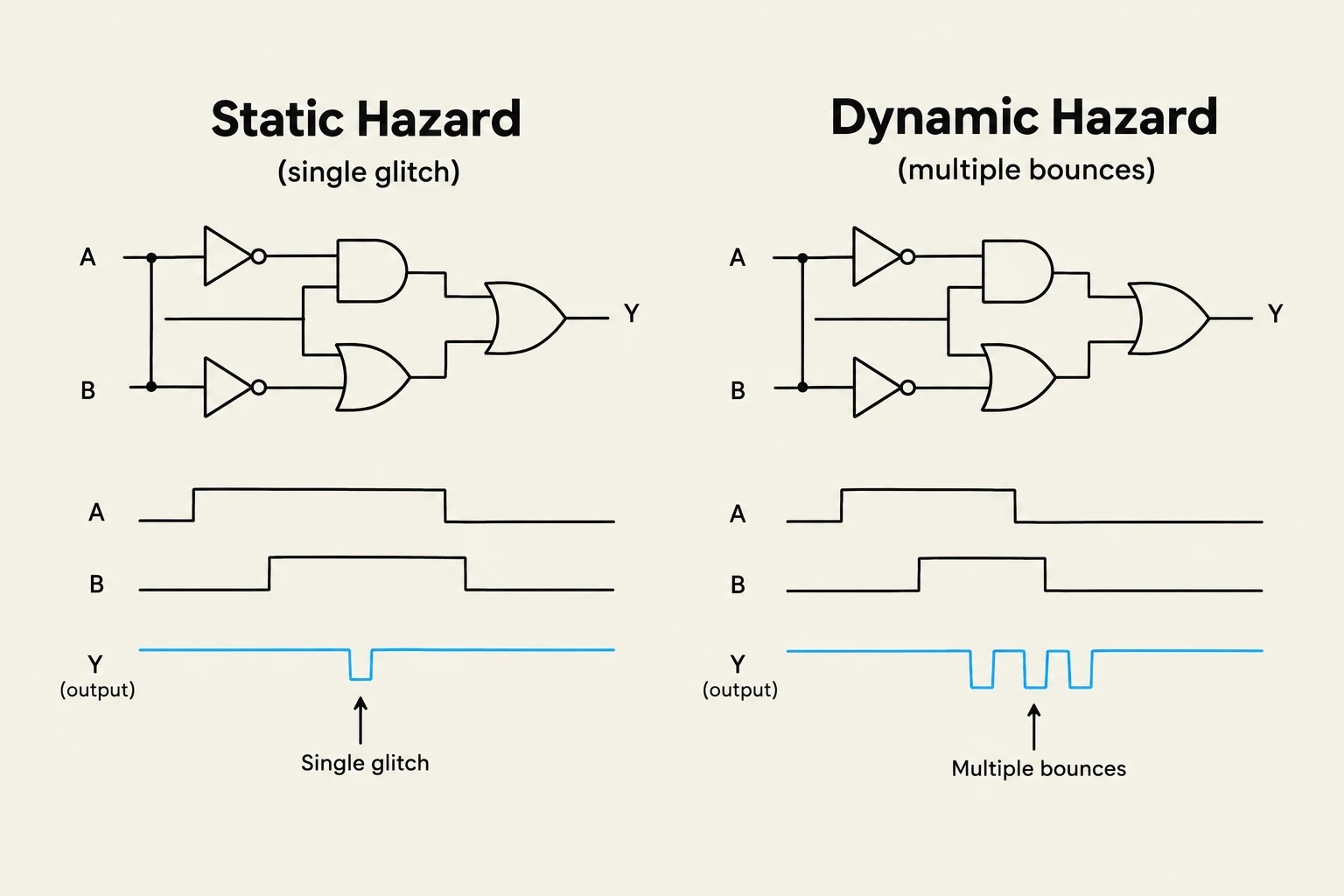
In an ideal world, digital logic behaves exactly as our Boolean equations predict. If an input changes, the output should transition smoothly to its new steady state. However, real-world hardware is governed by physics, specifically gate propagation delays. Because different paths through a circuit have different lengths and gate counts, signals arrive at different times. This discrepancy can cause the output to "glitch"—producing unwanted, momentary transitions that do not match the intended logic. These glitches are known as timing hazards.
Understanding Timing Hazards
A timing hazard occurs when a circuit's output produces a short pulse (a glitch) at a time when steady-state analysis predicts the output should remain constant. These are categorized based on how the output behaves during the transition.
Static Hazards
A static hazard occurs when the output is supposed to remain at a constant value but momentarily "flips" before returning to that value.
Static-1 Hazard: The output is supposed to be a constant 1, but it momentarily drops to 0 and then returns to 1.
Static-0 Hazard: The output is supposed to be a constant 0, but it momentarily jumps to 1 and then returns to 0.
Dynamic Hazards
A dynamic hazard is more complex. It occurs when the output changes multiple times during a single input transition. Instead of a single momentary glitch, the output "bounces."
Dynamic 0 to 1 hazard: The output transitions from 0→1→0→1.
Dynamic 1 to 0 hazard: The output transitions from 1→0→1→0.
This diagram illustrates static and dynamic hazards in digital logic circuits, showing how input signal glitches can affect the output.
The Root Cause: Multi-level Multi-paths
Why do dynamic hazards happen? The primary culprit is the presence of multi-level multi-paths. In a complex combinational circuit, a single input change may propagate through several different paths to reach the output. If these paths have unequal delays—due to different numbers of gates or different types of logic gates—the signals will arrive at the final gate at different times.
When these signals arrive out of sync, they can cause the output to cycle through intermediate, incorrect states before settling. While static hazards are often found in two-level Sum-of-Products (SoP) designs, dynamic hazards are frequently a symptom of deep, multi-level logic structures.
Designing Hazard-Free Combinational Circuits
In many practical applications, such as feedback-based sequential circuits, hazards can cause catastrophic errors. Therefore, engineers use specific techniques to minimize or eliminate them.
Eliminating Static Hazards
Static hazards in two-level SoP circuits can be detected using Karnaugh Maps (K-maps). If two adjacent groups of 1s (prime implicants) are not covered by a single overlapping term, a static-1 hazard may exist during the transition between those two groups.
To fix this, we add redundant consensus terms to the Boolean expression. By adding an extra product term that "bridges" the gap between the two adjacent groups, we ensure that the output remains 1 even during the transition.
Exam Tip: A properly designed two-level Sum-of-Products (AND-OR) circuit is inherently free of static-0 hazards, but it may still require extra terms to eliminate static-1 hazards.
Eliminating Dynamic Hazards
Dynamic hazards are harder to solve than static ones. One effective strategy is to rearrange the circuit from a multi-level structure into a two-level design. By reducing the number of levels, you limit the number of paths a signal can take, thereby reducing the opportunity for unequal delays to cause multiple transitions.
Another "brute force" approach for static hazards is to use all possible prime implicants in the design. While this ensures a hazard-free realization, it significantly increases the circuit's complexity and cost.
This diagram illustrates the difference between a multi-level logic circuit and a two-level sum-of-products circuit, highlighting how the latter can be simplified.
When Hazards Don't Matter: Synchronous Design
It is important to note that not every circuit requires a hazard-free design. In many modern digital systems, we use synchronous circuits.
In a synchronous system, all logic transitions are timed to occur between the clock edges. We use components like the D Flip-Flop, which only captures the input value at a specific moment (such as the rising edge of a clock). If the combinational logic settles into its correct steady state before the next clock edge arrives, any transient glitches or dynamic hazards that occurred in the interim will be ignored by the flip-flop.
Summary Table: Hazard Comparison
Hazard Type
Output Behavior
Primary Cause
Common Fix
Static-1
1→0→1
Unequal paths in SoP
Add redundant consensus terms
Static-0
0→1→0
Unequal paths in PoS
Add redundant consensus terms
Dynamic
0→1→0→1
Multi-level multi-paths
Reduce to two-level logic
By understanding these timing phenomena, designers can choose between the "brute force" of hazard-free combinational logic or the efficiency of synchronous, clock-driven architectures.
Keep reading for free.
Create an account to finish this reading and make it part of your study routine.