Entering the solar industry requires more than just technical knowledge of solar modules; it demands a rigorous commitment to safety and a deep understanding of the fundamental laws of electricity. Whether you are installing a small residential rooftop system or working on large-scale distributed generation (DG) projects—where electricity is produced near the point of consumption to reduce transmission losses—you must master the principles that keep you safe and ensure system efficiency.
Safety Basics: Protecting Yourself on Site
Safety in solar installation is categorized into three primary areas: fall protection, ladder safety, and electrical hazard mitigation.
Fall Protection and Ladder Safety
Falling is the leading cause of death in the construction industry. In residential solar, fall protection is mandatory at heights of 6 feet. The most common method used is the Personal Fall Arrest System (PFAS), which consists of a harness, a shock-absorbing lanyard, a lifeline, and an anchor. It is critical to remember that the anchor must be capable of holding at least 5,000 lbs.
When accessing roofs, ladder safety is paramount. Always use a 1:4 ladder ratio—for every 4 feet of height, move the base of the ladder 1 foot out from the wall. The ladder should extend at least 3 feet above the roofline to provide a safe transition. To prevent electrical conductivity, always use fiberglass ladders rather than metal ones, and always maintain three points of contact while climbing.
This illustration demonstrates the 1:4 ladder ratio, explaining that for every 4 feet of vertical height, the base of the ladder should be placed 1 foot away from the wall.
Electrical Hazards and Mitigation
Electrical work presents unique risks, most notably arc flashes. An arc flash is an explosive release of energy caused by an arc (a plasma discharge) that can be hotter than the sun. To protect against these, specialized Personal Protective Equipment (PPE), such as arc flash suits, goggles, and earplugs, must be worn.
To prevent fires and equipment damage, systems utilize Overcurrent Protection Devices (OCPD), such as fuses and circuit breakers. These devices "open" the circuit if the current exceeds safe limits. Furthermore, during maintenance, you must follow Lockout-Tagout (LOTO) procedures to ensure the system remains de-energized and cannot be accidentally turned back on while you are working.
Exam Tip: Safety standards are governed by OSHA at the federal and state levels, while the National Electric Code (NEC) provides the technical standards for safe installation. The Authority Having Jurisdiction (AHJ) is the entity (such as a local building inspector) that enforces these codes.
Electricity Basics: The Fundamentals
To design and troubleshoot PV systems, you must understand the relationship between voltage, current, resistance, and power.
Core Electrical Properties
Voltage (V): Often described as electrical pressure, measured in Volts.
Current (I): The actual flow of electricity, measured in Amperes (Amps).
Resistance (R): The opposition to the flow of current, measured in Ohms (Ω).
Power (P): The rate at which electricity is used, measured in Watts (W).
Energy (E): The total amount of electricity used over a specific period, measured in Watt-hours (Wh) or kilowatt-hours (kWh).
Ohm's Law and the Power Law
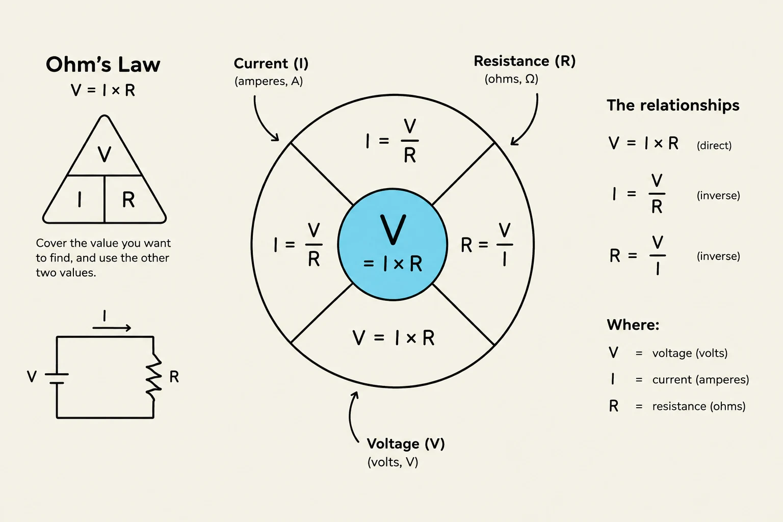
The relationship between these properties is governed by two primary mathematical laws. Ohm's Law defines how voltage, current, and resistance interact:
VIR=I⋅R=RV=IV
The Power Law allows us to calculate the rate of energy consumption:
P=V⋅I
Ohm's Law describes the relationship between voltage, current, and resistance in an electrical circuit. It states that voltage (V) is equal to current (I) multiplied by resistance (R). The law can be represented by a triangle, a circular diagram, and a simple circuit schematic, illustrating how to calculate any one of these variables if the other two are known.
Worked Example: Calculating Energy and Battery Capacity
If you have a 250W solar module operating for 5 hours, how much energy is produced?
EEE=P⋅Time=250W⋅5h=1250Wh (or 1.25 kWh)
When working with battery storage, you will often encounter Amp-hours (Ah). To find the total energy capacity in Watt-hours, use the following formula:
Wh=Ah⋅V
Circuit Connections and System Design
How you connect PV modules determines the electrical characteristics of your array.
Series vs. Parallel Connections
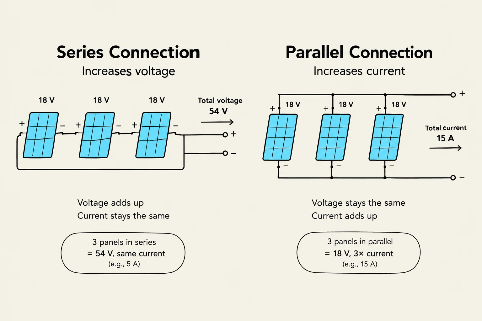
Series Connections: In a series connection, the positive terminal of one module is connected to the negative terminal of the next. This configuration increases the total voltage while the current remains the same as a single module.
Parallel Connections: In a parallel connection, all positive terminals are connected together, and all negative terminals are connected together. This configuration increases the total current while the voltage remains the same as a single module.
This diagram illustrates the difference between series and parallel connections of solar panels, showing how voltage and current are affected in each configuration.
Practical Considerations: Ampacity and Voltage Drop
When sizing wires, you must consider ampacity, which is the maximum amount of current a wire can carry before it becomes too hot and potentially melts its insulation. Additionally, as electricity travels through a conductor, some energy is lost due to resistance; this is known as voltage drop. Proper wire sizing is essential to minimize these losses and ensure the system performs as designed.
Finally, for troubleshooting and verification, a digital multimeter is an indispensable tool. It allows installers to measure voltage, current, and resistance to ensure the system is operating within the expected parameters.
Exam Tip: Remember that in the metric system used by the solar industry, "kilo" means 1,000, "mega" means 1,000,000, and "giga" means 1,000,000,000.
Keep reading for free.
Create an account to finish this reading and make it part of your study routine.