This project demonstrates how to transform analog environmental data (like temperature or light) into actionable digital intelligence using Analog-to-Digital Converters (ADC), Digital-to-Analog Converters (DAC), and digital processing techniques. It covers the engineering design cycle, including truth tables, Boolean a
In the field of digital electronics, one of the most practical applications of theory is the creation of a system that bridges the gap between the physical world and digital logic. The Smart Digital Room Environmental Monitor is a sophisticated project designed to demonstrate how analog environmental data—such as temperature or light levels—can be transformed into actionable digital intelligence. This project moves beyond simple logic gates, requiring the integration of signal conversion, digital processing, and decision-making logic to control real-world outputs.
Bridging the Analog-Digital Divide: ADC and DAC
The natural world is analog; temperature, light, and sound vary continuously. However, digital systems operate using discrete binary values (0s and 1s). To monitor a room, we must first use an Analog-to-Digital Converter (ADC). The ADC samples the continuous voltage from a sensor and converts it into a digital number that a processor or logic circuit can understand.
Once the digital decision is made (for example, "the room is too hot"), the system may need to interact with the physical world again. This is where a Digital-to-Analog Converter (DAC) becomes useful. A DAC takes a digital signal and converts it back into a varying voltage, which could be used to control the speed of a fan or the brightness of a dimmable light.
Digital Processing and Decision Logic
Once the sensor data is in digital form, the "intelligence" of the monitor begins. This stage involves digital processing, where the system evaluates the input against predefined thresholds. In a simple prototype, this is achieved through combinational logic, where the output is a direct function of the current inputs.
To design this logic, engineers follow a rigorous mathematical workflow:
Truth Tables: A complete list of all possible input combinations and their required outputs.
Boolean Expressions: Mathematical representations of the logic requirements using variables and operators (AND, OR, NOT).
Simplification: Using Boolean algebra or Karnaugh maps (K-maps) to reduce the complexity of the expression, ensuring the final circuit uses the fewest gates possible.
For example, if we want an LED to turn on only when the sensor reading is "High" AND the system is "Armed," our Boolean expression might look like:
Alarm=Sensorhigh⋅Systemarmed
Exam Tip: When deriving Boolean expressions, always double-check your Truth Table. A single error in the table will propagate through your K-map and result in a faulty circuit that is difficult to debug during physical construction.
Memory and Programmable Logic
Advanced environmental monitors do more than just react; they remember. This involves memory concepts, specifically the use of ROM (Read-Only Memory) and RAM (Random Access Memory). ROM might store fixed lookup tables for sensor calibration, while RAM could store historical data, such as the maximum temperature recorded in the last hour.
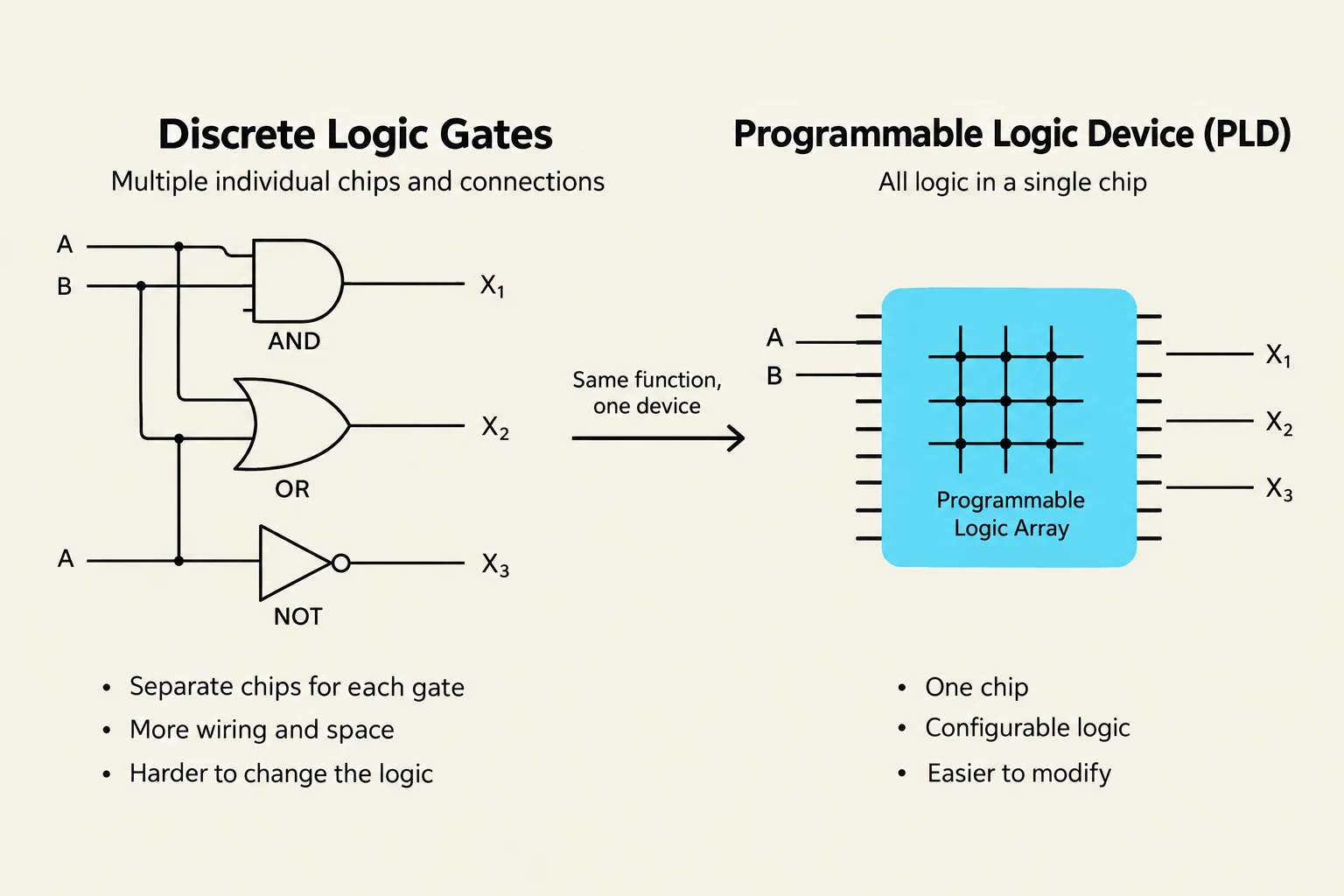
In modern design, rather than wiring hundreds of individual logic gates, we often use Programmable Logic Devices (PLDs). These are integrated circuits that can be programmed to implement any complex logic function, allowing for much higher density and flexibility in digital-system integration.
This diagram illustrates the difference between discrete logic gates and a programmable logic device (PLD), showing how multiple individual chips and connections can be consolidated into a single programmable logic array for the same function.
The Engineering Design Cycle
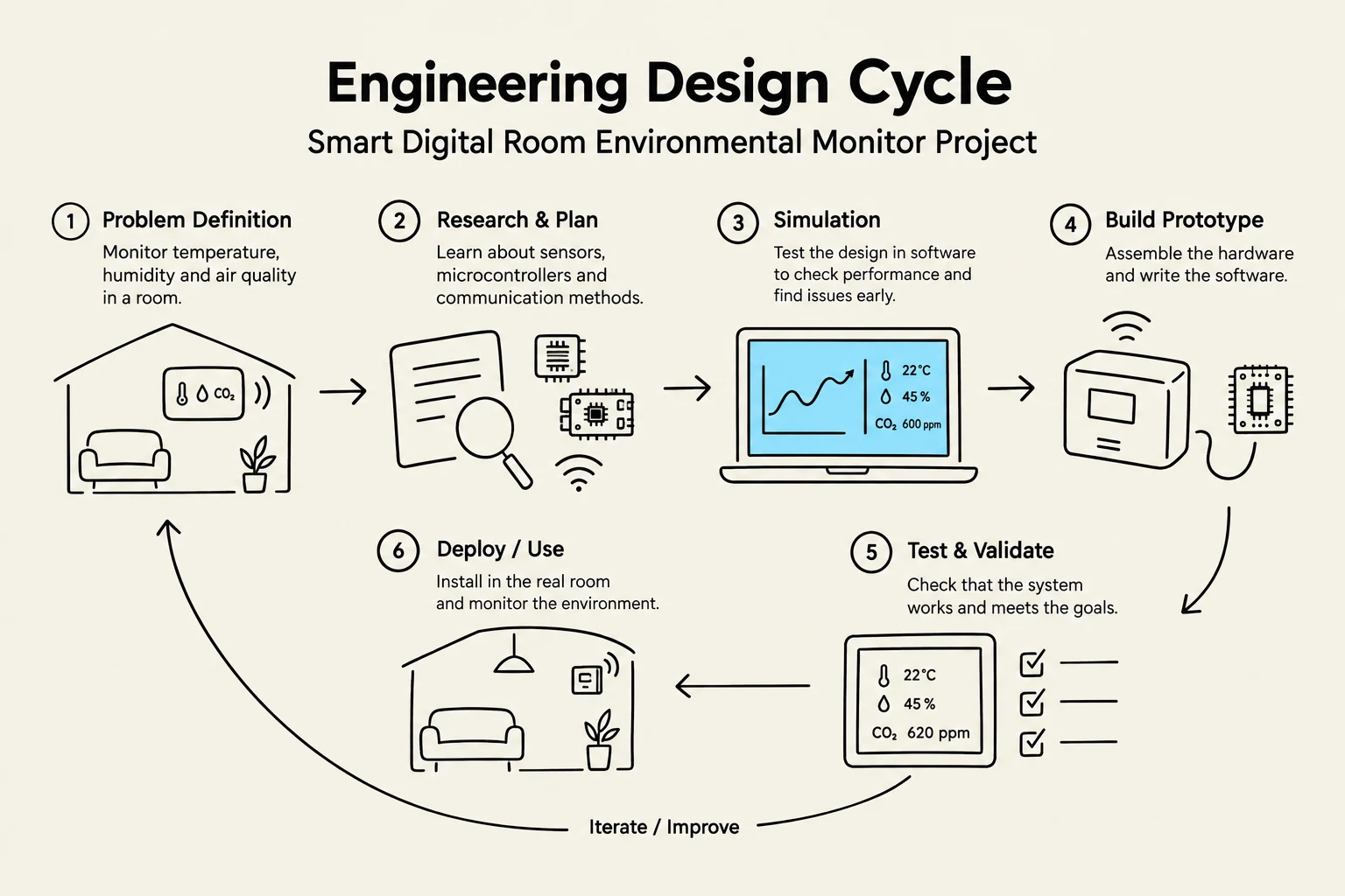
Building a functional prototype is not merely about plugging in wires; it is a disciplined engineering process. According to the project requirements, a student must move through a complete lifecycle: Problem Definition → Specifications → Truth/State Tables → Boolean Analysis → Circuit Schematic → Simulation → Physical Construction → Testing → Troubleshooting.
Simulation vs. Physical Construction
It is a critical rule in digital design that simulation is not the final project. While software tools allow you to verify your circuit schematic and ensure your logic is sound, they cannot account for real-world issues like electrical noise, loose connections, or component tolerances.
A successful engineer uses simulation as a tool to prove the theory works, but must then face the "real world" through physical construction and rigorous testing.
The engineering design cycle for a smart digital room environmental monitor project, illustrating steps from problem definition to iteration.
Summary of Implementation Steps
When approaching the Smart Environmental Monitor, keep this checklist in mind to ensure all technical requirements are met:
Define Thresholds: Determine the digital values that represent "NORMAL," "WARNING," and "CRITICAL" states.
Map the Logic: Create a State Table if your system needs to remember previous states (sequential logic) or a Truth Table for immediate reactions (combinational logic).
Optimize: Use K-maps to ensure your hardware implementation is efficient.
Verify: Test your prototype against predetermined cases (e.g., "Does the CRITICAL LED turn on exactly when the sensor hits the threshold?").
By following this structured approach, the project evolves from a simple collection of components into a robust, integrated digital system capable of monitoring and responding to its environment.
Keep reading for free.
Create an account to finish this reading and make it part of your study routine.