Radiographic Techniques in Endodontics: Horizontal and Vertical Shifts
Learn about radiographic horizontal and vertical shifts, including the SLOB rule, specialized projections, and their application in determining working length and visualizing root anatomy during endodontic treatment.
In endodontic clinical practice, a single two-dimensional radiograph often fails to reveal the true complexity of root canal anatomy. Superimposed structures, such as multiple canals or resorptive lesions, can hide critical details necessary for successful treatment. To overcome these limitations, clinicians utilize specific radiographic techniques involving horizontal and vertical shifts. By manipulating the angulation of the X-ray beam, practitioners can separate overlapping anatomy, visualize the tooth long axis, and accurately determine the working length of the canal.
Horizontal Shift and the SLOB Rule
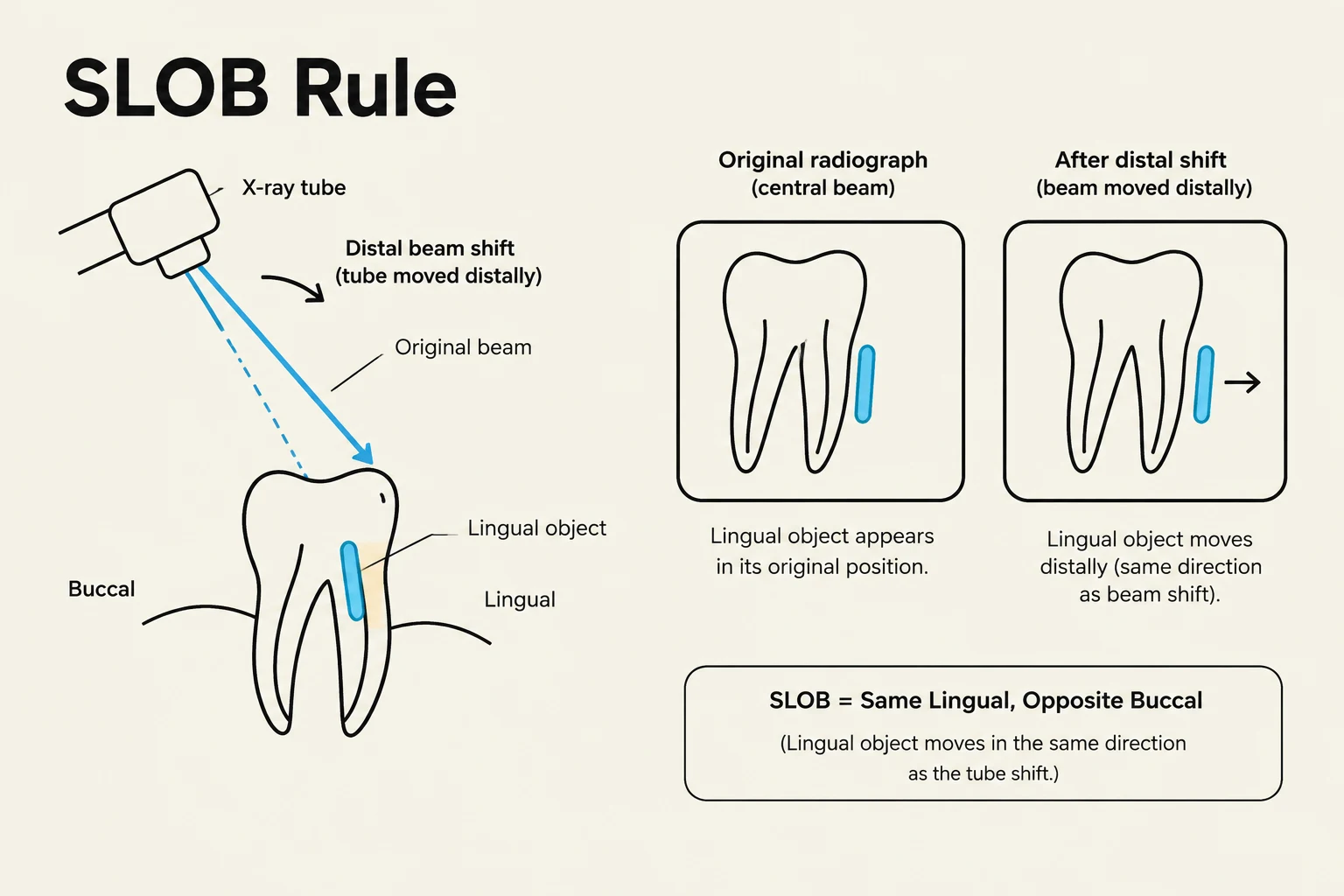
Horizontal shift refers to the movement of the X-ray beam along the mesiodistal axis to separate superimposed structures. This technique is essential when a clinician suspects more than one canal exists within a single root. To interpret the results of a horizontal shift, clinicians rely on the SLOB rule (Same Lingual, Opposite Buccal).
The SLOB rule dictates how an object moves on the radiograph relative to the direction of the X-ray beam shift:
Same Lingual: If the X-ray beam is shifted in the same direction as the object, the object will appear to move in the same direction on the radiograph, indicating it is in a lingual position.
Opposite Buccal: If the X-ray beam is shifted in the opposite direction of the object, the object will appear to move in the opposite direction, indicating a buccal position.
For example, in a mandibular molar, if you perform a distal beam shift, a lingual canal will move distally (same direction), while a buccal canal will move mesially (opposite direction).
The SLOB (Same Lingual, Opposite Buccal) rule illustrates how the position of a radiopaque object on a dental radiograph changes based on the direction of the X-ray beam shift. When the beam shifts distally, a lingual object appears to move in the same direction as the beam shift.
Specialized Horizontal Projections
Depending on the clinical goal, different horizontal projections may be used:
Straight-on (Orthoradial) Projection: This occurs when the tube head is positioned at a right angle to the buccal surface of the tooth. While useful for seeing the general volume of the pulp chamber or root curvature, it often results in the superimposition of mesial buccal and mesial lingual canals.
Mesial Angle Projection: By combining vertical and horizontal shifts, clinicians can achieve a mesial angle projection to separate specific canals for individual visualization.
Vertical Shift and Apex Visualization
Vertical shift involves changing the angulation of the X-ray beam along the long axis of the tooth. Unlike horizontal shifts, which are primarily used for separation, vertical shifts are critical for diagnostic accuracy and anatomical visualization.
The primary clinical applications for vertical shifts include:
Diagnosing root fractures.
Visualizing intracanal pins.
Avoiding the overlapping of orthodontic components, such as clasp wings.
Ensuring the apex is clearly visualized within the field of view.
Exam Tip: An incorrect vertical angle occurs when the beam is not perpendicular to the long axis of the tooth. This results in the apex falling outside the field of view, leading to an inaccurate and non-diagnostic image.
Diagram illustrating the correct and incorrect vertical angles for dental X-rays, showing how the apex of the tooth is captured within the field of view when the correct angle is used.
Regional Vertical Angulation Requirements
The required vertical angle varies significantly depending on the anatomical region of the mouth:
Region
Typical Vertical Shift/Angle
Maxillary Anterior Teeth
High shift (e.g., +40∘ or +20∘)
Maxillary Posterior Teeth
Moderate shift (e.g., +30∘ or +10∘)
Mandibular Region
Generally lower vertical angulation
Working Length (WL) Determination
Determining the working length is one of the most critical steps in endodontic therapy. The working length is defined by the distance from a coronal reference point to the apical constriction. It is important to note that the radiographic apex is not the same as the histological apical constriction; therefore, a radiograph alone is insufficient to establish the working length. Clinicians should use an electronic apex locator to find the constriction and a radiograph to verify the file position.
Ingle’s Method for Radiographic Verification
To verify the length using a radiograph, clinicians often use Ingle's Method:
Choose a coronal reference point (e.g., tip of a cusp or incisal edge).
Measure the initial length on a radiograph and subtract 2 mm.
Set the instrument to this new measurement (adjust the stopper).
Insert the instrument into the canal and take a new radiograph.
Measure the difference (X) between the instrument tip and the radiographic apex.
Adjustment Protocols
Once the difference X is measured, follow these protocols to ensure accuracy:
If X>0.5 mm long OR X>2 mm short of the apex: Adjust the length to X=1 mm short of the apex and verify with a new radiograph.
If X is between 0.5 mm long and 2 mm short of the apex: Adjust to X=1 mm without requiring additional radiographs.
The final working length should always be recorded as 1 mm short of the patency length.
Clinical Radiographic Stages
Successful endodontic treatment requires a sequence of specific radiographs to monitor progress and ensure a hermetic seal:
Preoperative Radiograph: Used to assess root curvature, number of canals, pulp chamber volume, and existing restorations or caries. Both straight and shift projections are recommended.
Working Length (WL) Radiograph: Taken after instrumentation and irrigation to verify the position of the Initial Apical File (IAF). A shift projection is typically used.
Master Cone Radiograph: Taken after the Master Apical File (MAF) is reached to verify the fit of the gutta-percha master cone.
Intermediate Fill Radiograph: Taken after seating the gutta-percha master cone with the root canal sealer to verify the fit and length.
Postoperative (Final) Radiographs: Taken after the permanent restoration (e.g., composite or post and crown) to confirm the success of the treatment.
Key Takeaway: A successful endodontic outcome is defined by a healthy, functional tooth within a healthy periapical environment. Radiographs are the primary tool to monitor the reduction of periapical radiolucency and subsequent bone regeneration over time.
Keep reading for free.
Create an account to finish this reading and make it part of your study routine.