Explores the critical intersection of mechanical mounting, structural integrity, and the mathematical rigor of string sizing for photovoltaic (PV) systems. Covers mounting options, load considerations, and temperature correction for voltage.
Designing a successful photovoltaic (PV) system requires more than just understanding how light converts to electricity; it requires a robust mechanical foundation and precise electrical calculations. A system that is electrically perfect but mechanically weak may fail under wind loads, while a system that is structurally sound but incorrectly sized for temperature variations can damage expensive inverters. This article explores the critical intersection of mechanical mounting, structural integrity, and the mathematical rigor of string sizing.
Mechanical Mounting Systems
The choice of mounting system is a primary driver of both installation cost and system performance. One of the most significant factors influenced by mounting is thermal management. Because PV modules lose efficiency as they heat up, the airflow provided by the mounting structure is vital. Increased airflow helps dissipate heat, which helps maintain higher voltage and overall power, following the fundamental relationship:
Power=Volts×Amps
Residential and Building Integrated Options
For residential applications, flush mounted systems are common on sloped roofs, where modules follow the existing roofline. To ensure adequate cooling, designers should aim to maintain a 3-to-6-inch gap between the modules and the roof surface.
In contrast, Building Integrated PV (BIPV) involves using PV modules as the actual roofing material itself. While aesthetically pleasing, BIPV typically suffers from reduced airflow and higher operating temperatures, which can lead to lower efficiency compared to traditional mounted modules.
Low Slope and Flat Roof Systems
Flat roofs present unique challenges regarding wind and water management. There are two primary approaches:
Ballasted Systems: These use heavy weights, such as concrete blocks, to hold the array in place. This is often preferred when roof penetrations must be avoided to prevent leaks.
Penetrating Systems: These involve structural attachments, such as posts or standoffs, that are anchored directly into the roof's rafters or trusses.
Ground Mounts and Tracking
For utility-scale projects, ground mounts are the standard. These systems offer superior airflow and can be stabilized using piles (steel driven into the earth) or ground screws.
To maximize energy harvest, many ground-mounted systems utilize tracking systems to follow the sun's path.
Single-axis trackers rotate on a horizontal axis and are common in large-scale solar farms.
2-axis trackers follow both azimuth and altitude, providing even higher yields but with increased complexity; these are often paired with Concentrating PV technologies.
Diagrams illustrating single-axis and two-axis solar trackers, showing their rotational capabilities for following the sun.
Structural Considerations and Loads
A PV array acts like a sail in the wind and a heavy weight on the structure. Engineers must design for several specific types of loads to ensure long-term safety:
Wind Loads: Measured in pounds per square foot (Psf), these forces can be immense, particularly at the corners and edges of a roof.
Snow Loads: Accumulated snow adds significant weight. In high-latitude areas, designers might use lower tilt angles to prevent excessive accumulation, though this must be balanced against shading concerns.
Dead Loads: This refers to the permanent weight of the PV modules, racking, and mounting hardware.
Live Loads: These are temporary weights, such as technicians performing maintenance or workers walking on the roof.
String Sizing and Temperature Correction
String sizing is the process of determining how many modules to connect in series to ensure the array operates within the safe voltage limits of the inverter or charge controller. Because the voltage of a PV module changes significantly with temperature, designers must perform "voltage temperature correction".
Cold Temperature Sizing (Maximum Voltage)
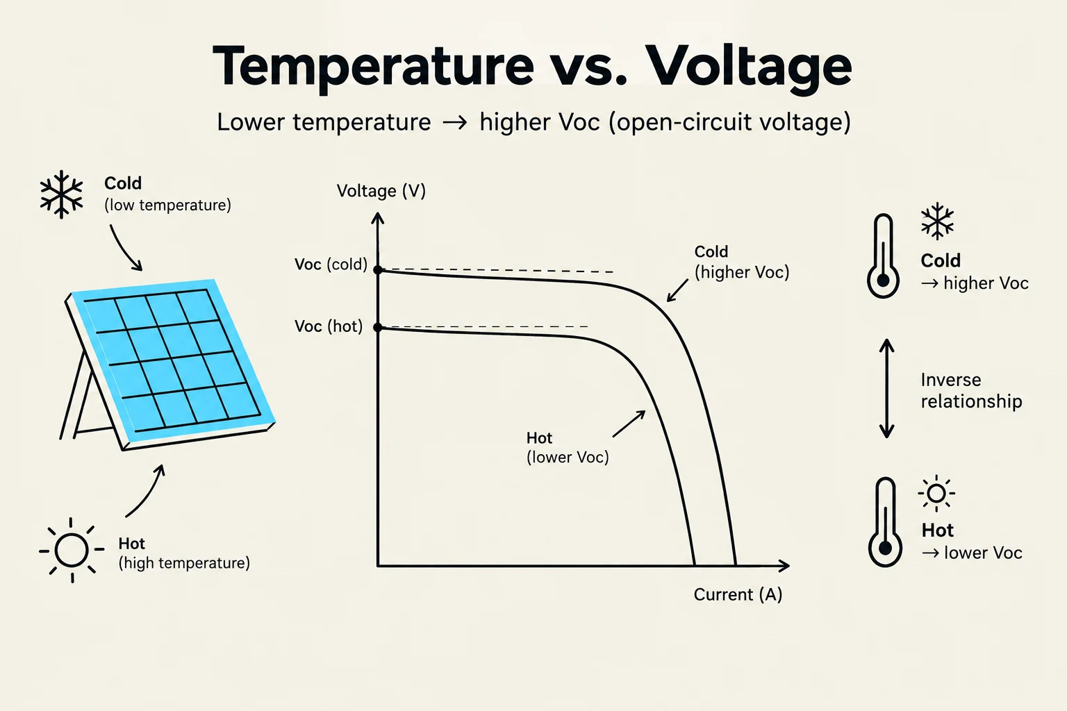
As the temperature decreases, the open-circuit voltage (Voc) of a module increases. If a string is too long, a very cold morning could cause the voltage to exceed the Maximum Input Voltage of the inverter, potentially destroying the equipment.
To prevent this, designers use the Temperature Coefficient of Voc to calculate the corrected voltage at the coldest expected temperature for the site.
Exam Tip: When calculating the maximum number of modules for a string based on cold temperatures, always round down to ensure you never exceed the inverter's limit.
The calculation follows this logic:
Calculate the temperature difference (ΔT) from the standard 25∘C test condition.
Apply the temperature coefficient to find the corrected Voc,cold.
Use the formula:
Max Modules=Voc,coldMax Inverter Voltage
Hot Temperature Sizing (Minimum Voltage)
Conversely, as temperature increases, the maximum power voltage (Vmp) decreases. If the modules get too hot, the voltage might drop below the Minimum Input Voltage required by the inverter to operate, causing the system to shut down or lose efficiency.
Exam Tip: When calculating the minimum number of modules required to keep the system running in the heat, always round up.
The formula for hot temperature sizing is:
Min Modules=Vmp,hotMin Inverter Voltage
This graph illustrates the relationship between temperature and voltage in a solar panel, showing that lower temperatures result in a higher open-circuit voltage (Voc).
Commissioning and Maintenance
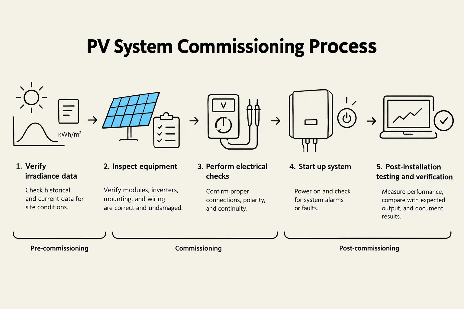
Once the mechanical and electrical design is implemented, the system must undergo commissioning. This involves verifying that the installation matches the design and that the system performs according to expected irradiance data.
Ongoing maintenance is essential for longevity. For systems utilizing energy storage, battery maintenance (such as checking for terminal corrosion or managing charge cycles) is a critical component of system health. Furthermore, ensuring that anti-islanding requirements are met is a vital safety protocol; this ensures that grid-tied inverters automatically disconnect during a utility power outage to protect workers.
The PV System Commissioning Process outlines the steps involved in setting up a photovoltaic system, from verifying irradiance data and inspecting equipment to performing electrical checks, starting up the system, and conducting post-installation testing.
Keep reading for free.
Create an account to finish this reading and make it part of your study routine.