Explore the fundamental principles of memory hierarchy in computer architecture, including locality, inclusion, and coherence. Learn about performance modeling techniques for two-level and multilevel systems, covering access time, efficiency, and cost.
In modern computer architecture, a fundamental tension exists between the speed of the processor and the capacity of memory. While processors operate at incredibly high frequencies, the large-scale storage required to hold modern datasets is inherently slower and more expensive. To bridge this "performance gap," designers employ a memory hierarchy—a layered structure of storage elements ranging from small, lightning-fast registers to massive, slower secondary storage.
The goal of a well-designed hierarchy is to provide the processor with the illusion of a memory system that is as fast as its fastest component and as large as its largest component.
Fundamental Design Principles
The effectiveness of a memory hierarchy is not accidental; it relies on three core principles: locality, inclusion, and coherence.
Locality
Locality is the principle that makes hierarchy possible. It refers to the tendency of a processor to access a relatively small subset of data at any given time. There are two primary types:
Temporal Locality: If a particular memory location is referenced, it is likely to be referenced again in the near future.
Spatial Locality: If a particular memory location is referenced, it is likely that nearby memory locations will be referenced soon.
A graph showing the probability distribution curve decreasing over time to illustrate temporal locality in memory.
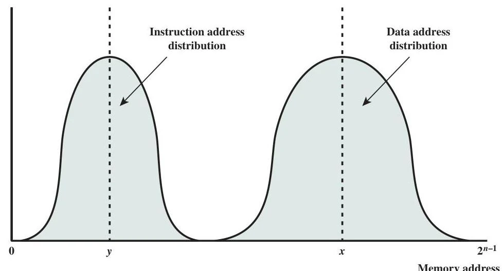
This graph illustrates the distribution of instruction and data addresses in memory, showing two distinct peaks representing common address ranges for each.
Inclusion
The principle of inclusion dictates how data moves through the layers. Data resides in the most remote (slowest) level, Mn, and is copied into closer (faster) levels, such as Mn−1 or Mn−2, as it is needed for processing.
Coherence
As data is copied across multiple levels, the system must ensure that all copies remain consistent. This is addressed through two types of coherence:
Vertical Coherence: Ensures that updates made in a fast, upper level are eventually propagated to the slower, lower levels.
Horizontal Coherence: In systems with multiple processors or multiple caches at the same level, horizontal coherence ensures that if one cache updates a piece of data, all other caches sharing that level are alerted to the change to prevent them from using stale data.
Exam Tip: When discussing coherence, remember that Vertical refers to the relationship between levels (e.g., L1 to Main Memory), while Horizontal refers to the relationship between peer components (e.g., Core 1's L1 to Core 2's L1).
Performance Modeling: Two-Level Systems
To evaluate a hierarchy, designers use mathematical models to predict how much time the processor will spend waiting for data. For a simple two-level system, the average system access time (Ts) is calculated based on the access time of the upper level (T1), the access time of the lower level (T2), and the hit ratio (H).
The hit ratio H represents the fraction of memory references found in the first level (M1). The formula is:
Ts=T1+(1−H)×T2
Access Efficiency
A critical metric for designers is access efficiency, which is the ratio of the upper-level access time to the total average access time:
Efficiency=TsT1
If the latency gap between T1 and T2 is large, maintaining a very high hit ratio is essential to prevent the system performance from collapsing toward the speed of the slower memory.
Cost Modeling
Designers must also balance performance with cost. The average cost per bit (Cs) for a two-level system is a weighted average of the costs of the two levels (C1 and C2) and their respective sizes (S1 and S2):
Cs=S1+S2C1S1+C2S2
An effective design ensures that Cs≈C2 by keeping the expensive, high-speed memory (S1) significantly smaller than the cheap, high-capacity memory (S2).
Multilevel Hierarchies
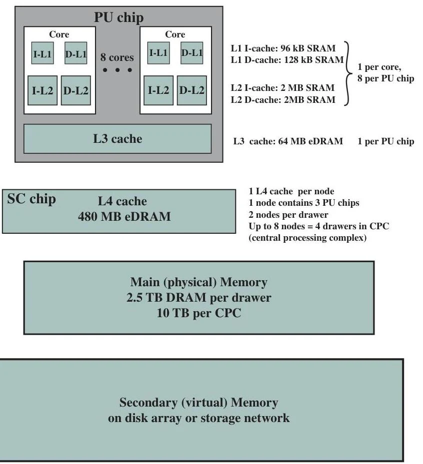
Modern architectures are far more complex than two-level systems. For example, the IBM z13 utilizes a sophisticated hierarchy including multiple cache levels (L1, L2, L3, and L4), main storage (DRAM), and secondary memory (disks).
This diagram illustrates the memory hierarchy of a computing system, detailing the structure of PU chips, SC chips, main memory, and secondary memory, along with their respective cache sizes and capacities.
In an n-level system, performance is modeled using conditional probabilities. Let hi be the probability that data is found in level Mi, given that it was not found in the previous level Mi−1. The total access time Ts is minimized when the hit ratios at each level are maximized.
The hierarchy typically follows this progression:
Caches (L1, L2, L3, L4): Extremely fast, semiconductor-based memory located near or on the processor.
Main Storage (DRAM): Larger, slower semiconductor memory that holds the active working set of the operating system and applications.
Secondary Memory: Massive, non-volatile storage such as hard disks or SSDs used for long-term data retention.
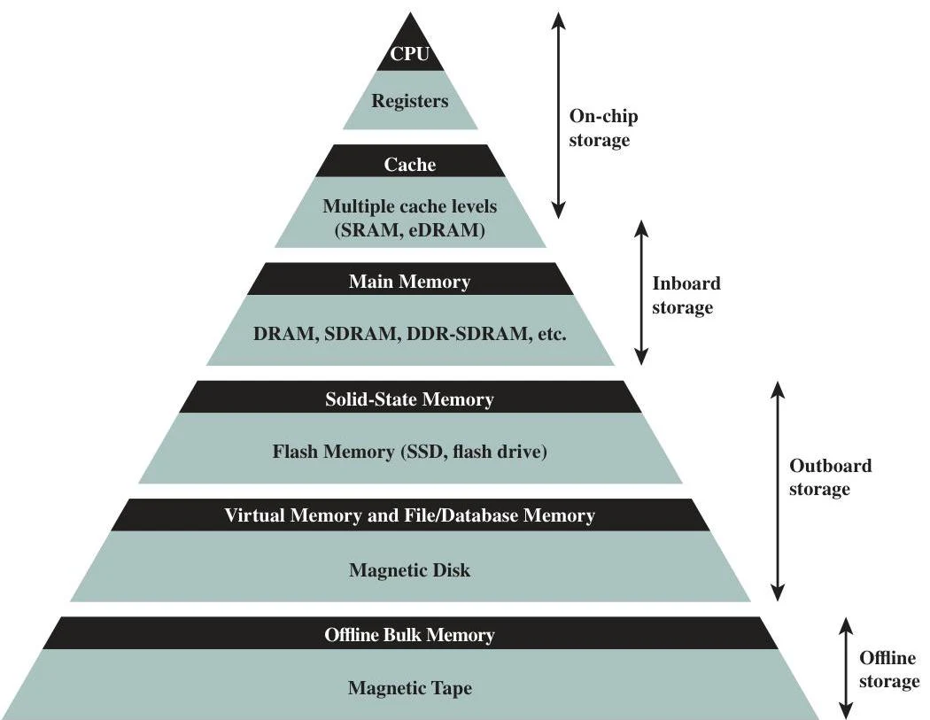
A pyramid diagram illustrating different levels of computer memory and storage, from fastest and smallest (CPU registers) to slowest and largest (magnetic tape).
By layering these technologies, designers can create systems that satisfy the competing requirements of high speed, massive capacity, and low cost.
Keep reading for free.
Create an account to finish this reading and make it part of your study routine.