Explore the fundamentals of Boolean algebra, logic levels, and basic logic gates (AND, OR, NOT) that form the foundation of digital electronics and computing.
Digital electronics form the backbone of modern computing, and at the heart of these systems lies Boolean algebra. Unlike the ordinary algebra used in mathematics to represent continuous numbers, Boolean algebra is a branch of mathematics that deals with variables that can only exist in one of two states. This binary nature allows us to model the behavior of electronic circuits using logic.
Boolean Variables and Logic Levels
In Boolean algebra, variables do not represent quantities, but rather "logic levels". A variable can only take one of two possible values: 0 or 1. These values can be represented in various ways depending on the context of the circuit:
Logic 0
Logic 1
False
True
Off
On
Low
High
No
Yes
Open Switch
Close Switch
Logic Gates and Truth Tables
Digital circuits are constructed using logic gates, which are physical components (made from diodes, transistors, and resistors) that perform specific logical operations on input signals to produce an output.
To understand how a specific gate behaves, we use a truth table. A truth table is a mathematical tool that lists every possible combination of input logic levels and shows the resulting output level.
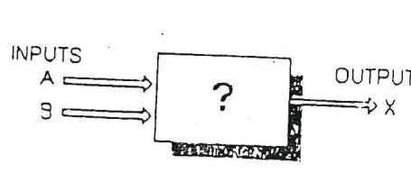
A diagram illustrating a generic logic gate with two inputs labeled A and B, and one output labeled X, with the internal function represented by a question mark.
For example, if we have a circuit with inputs A and B and an output X, the table below shows the relationship for an OR operation:
A
B
X=A+B
0
0
0
0
1
1
1
0
1
1
1
1
Basic Logic Operations
There are three fundamental operations that serve as the building blocks for all digital systems: AND, OR, and NOT.
The OR Operation
The OR operation is represented by the expression X=A+B. In this context, the "$+$" symbol does not represent arithmetic addition, but rather the logical "OR". The output is 1 if at least one of the inputs is 1.
The AND Operation
The AND operation is represented by the expression $X = AB$. The output is 1 only if both inputs A and B are 1.
The NOT Operation (Inverters)
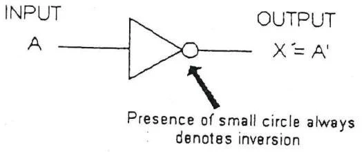
The NOT operation is also known as inversion or complementation. A NOT gate, or inverter, simply flips the logic level of the input. If the input is A, the output is written as $A'$ (read as "A prime").
This diagram illustrates a digital logic inverter gate, where the small circle at the output signifies signal inversion.
The relationship is defined as:
1′0′=0=1
Combined Operations: NAND and NOR
In practical digital design, we frequently use gates that combine the basic operations. These are often identified by a small circle on the gate symbol, which represents an inversion.
The NOR Operation
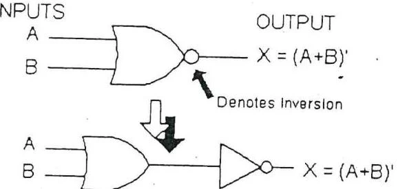
A NOR gate is an OR gate followed by an inverter. Its output expression is:
X=(A+B)′
This diagram illustrates the logic of a NOR gate, showing its symbol and equivalent representation as an OR gate followed by an inverter. The equation X = (A+B)' represents the output X as the negation of the logical OR of inputs A and B.
The NAND Operation
A NAND gate is an AND gate followed by an inverter. Its output expression is:
X=(AB)′
This diagram illustrates the logic gate symbol for a NAND gate and its equivalent representation using an AND gate followed by an inverter. The output X is defined as the logical NOT of the product of inputs A and B, represented as X = (AB)'.
The Universality of NAND and NOR Gates
One of the most important concepts in digital logic is that NAND and NOR gates are "universal." This means that any possible Boolean expression—and therefore any digital circuit—can be implemented using only NAND gates or only NOR gates.
Boolean Expressions and Circuit Implementation
Complex circuits are described using Boolean expressions. When evaluating these expressions, there is a specific order of operations to follow:
Perform all single-term inversions (e.g., $0' = 1$).
Perform operations inside parentheses.
Perform AND operations before OR operations (unless parentheses dictate otherwise).
If an expression has a bar over it, perform the operations under the bar first, then invert the result.
For example, to evaluate $X = A'BC(A+D)'$ where $A=0, B=1, C=1, D=1$:
X=A′BC(A+D)′=0′⋅1⋅1⋅(0+1)′=1⋅1⋅1⋅(1)′=1⋅1⋅1⋅0=0
Boolean Theorems and Simplification
To make digital circuits more efficient, we use Boolean theorems to simplify complex expressions. Simplifying an expression reduces the number of gates required, which lowers cost and power consumption.
Fundamental Theorems
Some basic rules include:
Identity:X+0=X and X⋅1=X
Null Elements:X+1=1 and X⋅0=0
Idempotency:X+X=X and X⋅X=X
Involution: $(X')' = X$
Multivariable Theorems
When dealing with multiple variables, we use laws such as:
Commutative Law:x+y=y+x and $xy = yx$
Associative Law:x+(y+z)=(x+y)+z
DeMorgan's Theorem
DeMorgan's theorems are essential for simplifying expressions where a sum or product is inverted.
The complement of a sum is equal to the product of the complements:
(x+y)′=x′⋅y′
The complement of a product is equal to the sum of the complements:
$(xy)' = x' + y'$
These theorems allow designers to switch between different gate types, such as converting a NOR gate into an AND gate with inverted inputs.
Advanced Theorems
Shannon's Expansion Theorem: This theorem allows a function to be expressed in terms of a single variable and its complement:
F(X1,X2,…,Xn)=X1⋅F(1,X2,…,Xn)+X1′⋅F(0,X2,…,Xn)
Principle of Duality: This principle states that any theorem or identity in switching algebra remains true if 0 and 1 are swapped and the operators ($+$ and ⋅) are swapped.
Exam Tip: Evaluating Expressions
When you encounter a long Boolean expression, always look for DeMorgan's applications first. It is often the fastest way to break down large "bars" over multiple terms and simplify the expression into manageable pieces.
Keep reading for free.
Create an account to finish this reading and make it part of your study routine.