Dynamics Tutorial: Mastering Free-Body Diagrams and Newton's 2nd Law
Learn the essential tools for solving dynamics problems in physics: Free-Body Diagrams (FBDs) and Newton's 2nd Law. This guide covers vector and component forms, common forces, and applying these concepts to scenarios like pushing a box up an incline.
In the study of physics, moving from simple kinematics to the complex world of forces requires a fundamental shift in how we visualize the world. This shift occurs in the field of Dynamics, where we investigate not just how objects move, but why they move. One of the most common challenges students face is translating a physical scenario—such as a box being pushed up a ramp—into a mathematical framework that can be solved.
This article serves as a guide to the essential tools used in dynamics: the Free-Body Diagram (FBD) and the application of Newton's 2nd Law in both vector and component forms.
Understanding Dynamics and Newton's 2nd Law
Dynamics is the branch of mechanics concerned with the motion of bodies under the action of forces. To solve any problem in this field, we rely on the cornerstone of classical mechanics: Newton's 2nd Law.
At its most fundamental level, Newton's 2nd Law states that the net force acting on an object is equal to the mass of that object multiplied by its acceleration. In its vector form, this is expressed as:
∑F=ma
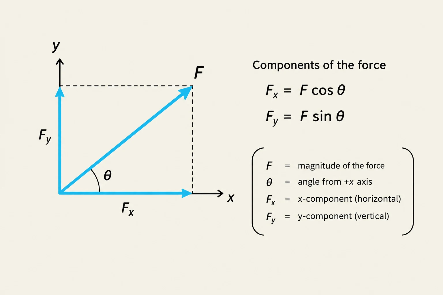
While the vector form is elegant, it is often difficult to use directly in calculations because acceleration and force can point in any direction in 3D space. To make these problems solvable, we must break these vectors down into components—typically along the x and y axes.
This diagram illustrates the components of a force vector F, showing its horizontal (Fx) and vertical (Fy) components in relation to the angle θ it makes with the x-axis. The equations Fx = F cos θ and Fy = F sin θ are provided, along with definitions for F, θ, Fx, and Fy.
The Essential Tool: Free-Body Diagrams (FBD)
Before you can write a single equation, you must perform a "visual audit" of the forces acting on your object. This is done through a Free-Body Diagram (FBD).
An FBD is a simplified sketch where the object is represented as a single point (a particle) and all external forces acting upon it are drawn as arrows pointing away from that point. When drawing an FBD, you must be disciplined. Do not include "internal" forces or forces that the object exerts on its surroundings; only include forces that are applied to the object.
Common forces to look for include:
Gravity (Fg or mg): Always points straight down toward the center of the Earth.
Normal Force (FN): Always perpendicular to the surface of contact.
Friction (f): Acts parallel to the surface, opposing the direction of motion or intended motion.
Applied Force (Fapp): The push or pull exerted by an external agent.
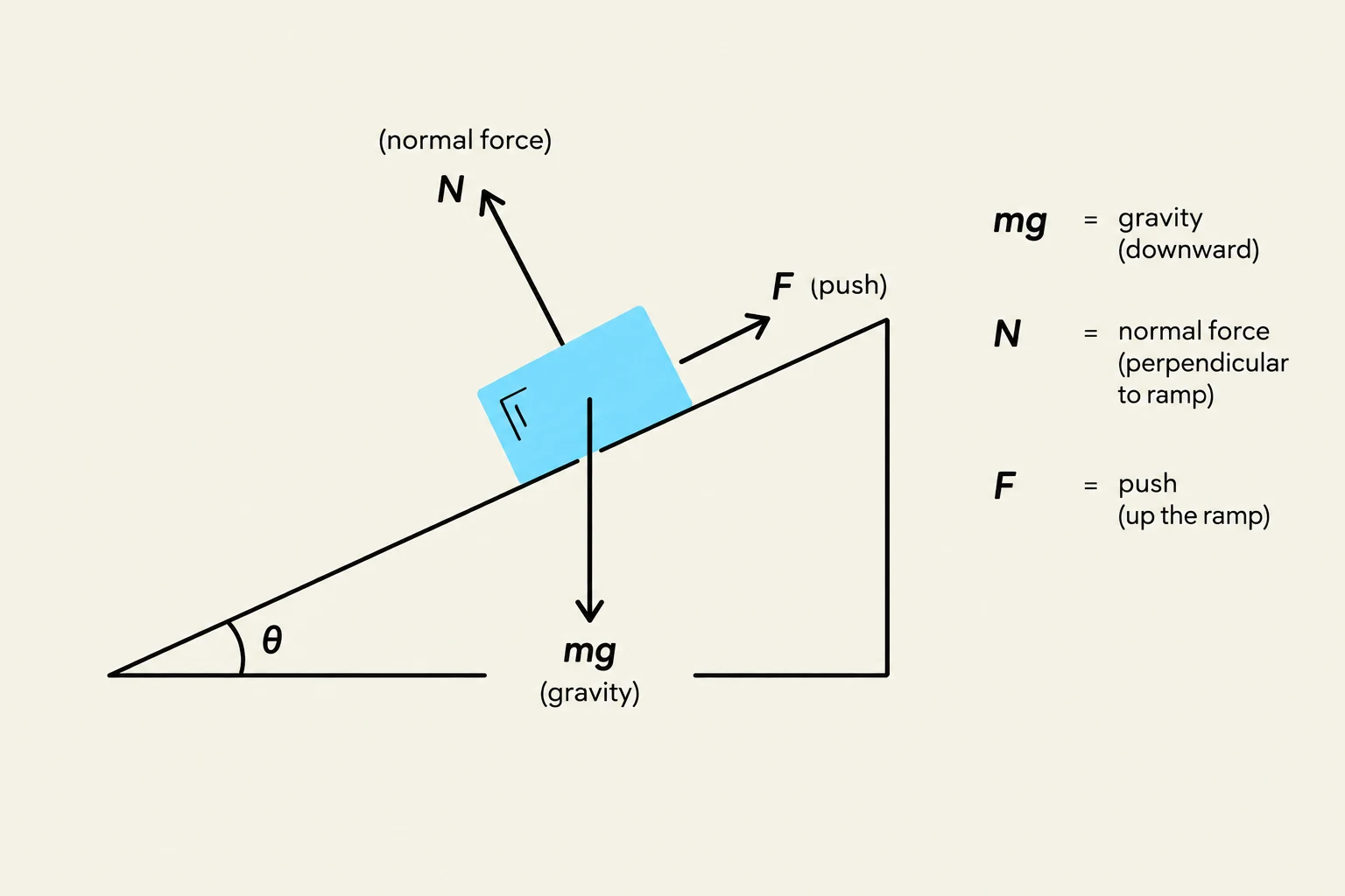
Diagram illustrating forces acting on a block on an inclined plane, including gravity, normal force, and an applied push force.
Exam Tip: A common mistake is to draw the Normal Force as being "up." Remember, the Normal Force is always perpendicular to the surface. If the surface is tilted, the Normal Force is tilted!
Application: Pushing a Box up an Incline
Let's apply these concepts to a classic problem: pushing a box up an incline at an angle θ.
When dealing with inclines, the standard x-y coordinate system (where y is vertical) is often inconvenient. Instead, we rotate our coordinate system so that the x-axis is parallel to the incline and the y-axis is perpendicular to it. This simplifies the math because the object's acceleration will likely only have a component along the x-axis.
Step 1: Identify the Components
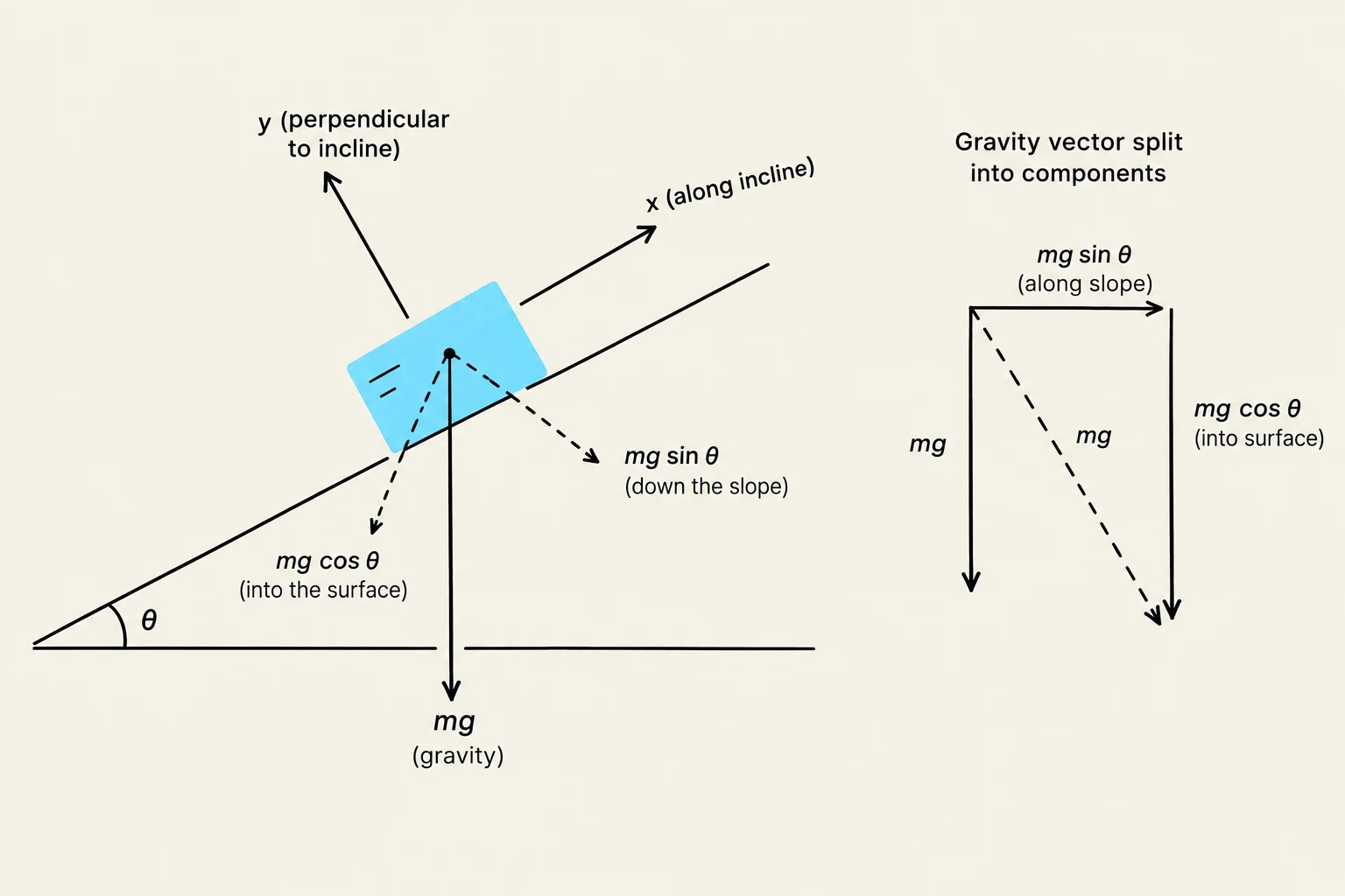
Once we rotate our axes, we must re-calculate our force components. Gravity, which always points straight down, now has two components relative to our new axes:
Perpendicular component:Fg,y=mgcos(θ)
Parallel component:Fg,x=−mgsin(θ) (the negative sign indicates it pulls the box down the ramp).
Step 2: Write Newton's 2nd Law in Components
Now, we write the sum of forces for each axis separately.
For the y-direction (perpendicular to the ramp):
Since the box isn't jumping off the ramp or sinking into it, the acceleration in the y-direction is zero (ay=0).
∑Fy=FN−mgcos(θ)=0
For the x-direction (parallel to the ramp):
If we are pushing the box up with a force Fapp and there is friction f acting against us:
∑Fx=Fapp−f−mgsin(θ)=max
Diagram illustrating the decomposition of gravitational force (mg) acting on an object on an inclined plane into components parallel (mg sin θ) and perpendicular (mg cos θ) to the slope.
Summary Checklist
To master dynamics problems, follow this workflow every time:
Isolate the object: Decide exactly what you are analyzing.
Draw the FBD: Represent the object as a dot and draw all external force vectors.
Choose a coordinate system: For inclines, align your axes with the surface.
Decompose vectors: Use trigonometry to break diagonal forces into x and y components.
Apply ∑F=ma: Write a separate equation for each dimension.
By mastering these steps, you move from "guessing" the answer to systematically deriving it through the laws of physics.
Keep reading for free.
Create an account to finish this reading and make it part of your study routine.