In the field of medical ultrasound, understanding how sound waves interact with human tissue is fundamental to creating clear diagnostic images. When a sound beam travels through the body, it does not simply pass through unimpeded; it encounters various boundaries, or interfaces, that cause the energy to behave in specific ways. Some energy is reflected back to the transducer to create an image, some is transmitted deeper into the body, and some is lost to heat or scattering. The primary driver behind these behaviors is a physical property known as acoustic impedance.
Acoustic Impedance
Acoustic impedance (also known as characteristic impedance) describes the relationship between acoustic pressure and the speed of particle vibrations in a sound wave. Essentially, it tells us how much a medium resists the motion of the sound wave passing through it.
The value of acoustic impedance (Z) is determined by two main factors: the density of the medium (ρ) and the velocity of sound within that medium (c). The mathematical relationship is expressed as:
Z=ρ⋅c
The units used to measure impedance are Rayls. Because different tissues have different densities and stiffnesses, they possess different Z values. For example, bone has a much higher impedance than soft tissue, which in turn is much higher than air.
Key Concept: Impedance does not depend on the frequency of the ultrasound beam.
The Interface and Impedance Mismatch
When a sound wave traveling through one medium hits a boundary between two different media, this boundary is called an interface. The difference between the acoustic impedances of the two media at this interface is known as an impedance mismatch.
The magnitude of this mismatch dictates how much of the sound energy is reflected versus how much is transmitted. If the impedance is identical across an interface, no reflection will occur. However, the larger the difference in Z values, the stronger the reflection will be.
Intensity Reflection and Transmission Coefficients
To quantify exactly how much sound is reflected or transmitted at an interface, we use two specific coefficients:
Intensity Reflection Coefficient (IRC): This represents the fraction of the incident intensity that is reflected at the interface. It can be calculated using the Z values of the two media (Z1 and Z2):
IRC=(Z2+Z1Z2−Z1)2
Intensity Transmission Coefficient (ITC): This represents the fraction of the incident intensity that continues into the second medium. Since energy must be conserved, the sum of the reflected and transmitted intensity must equal the original intensity:
ITC=1−IRC
Exam Tip: A high impedance mismatch (like soft tissue to air) results in a very high IRC, meaning almost all sound is reflected and very little is transmitted. This is why ultrasound gel is required to eliminate air between the transducer and the skin.
Worked Example: Bone vs. Soft Tissue
Let's calculate the reflection and transmission at an interface between bone and soft tissue using the following values:
When sound hits an interface, it can behave in two distinct ways: it can reflect (bounce back) or refract (bend).
Reflection
Reflection is the sound that returns to the probe to create an image. There are two main types:
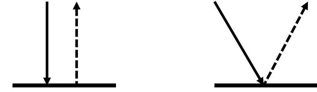
Specular Reflection: Occurs when the sound beam hits a large, smooth surface (greater than one wavelength in diameter), such as the diaphragm. The angle of incidence will always equal the angle of reflection.
Non-specular (Scatter): Occurs when sound interacts with small or rough surfaces.
Diagram illustrating the concepts of absorption and reflection of light.
Refraction
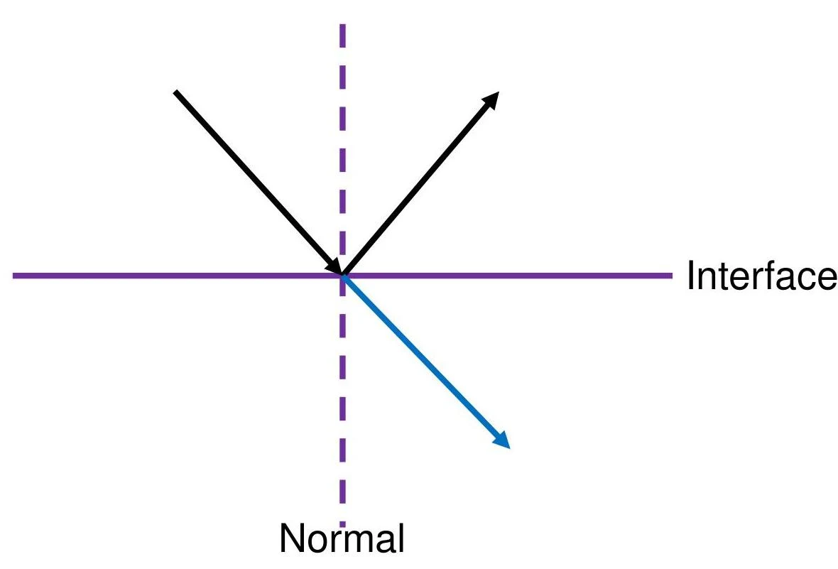
Refraction refers to the bending of the sound beam as it is transmitted across an interface. Refraction occurs only when two conditions are met:
The velocities of the two media are different (V1=V2).
The angle of incidence is non-perpendicular.
Sound follows Snell's Law, which describes how much the beam will bend based on the velocity change:
sinθtsinθi=vtvi
If V1>V2, the sound bends towards the normal.
If V1<V2, the sound bends away from the normal.
If the angle reaches a certain "critical value" when V1<V2, Total Internal Reflection can occur, where no sound is transmitted at all.
A diagram illustrating the reflection and refraction of light at an interface. The purple line represents the interface between two media, and the dashed purple line represents the normal to the interface. The black arrow shows an incident ray and a reflected ray, while the blue arrow shows a refracted ray.
Other Factors in Attenuation
While reflection and refraction are key interactions, they are part of a broader phenomenon called attenuation—the weakening of the sound beam as it travels. Other contributors to attenuation include:
Absorption: The conversion of sound energy into heat. This is the dominant factor in attenuation, accounting for roughly 80% of the loss.
Scatter: The result of sound interacting with interfaces smaller than a wavelength. This creates the "grainy" internal texture (parenchyma) of organs seen on ultrasound.
Wave-front Divergence: The natural spreading of the sound beam as it travels, which increases the area the beam covers and thus decreases its intensity.
Keep reading for free.
Create an account to finish this reading and make it part of your study routine.